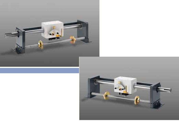
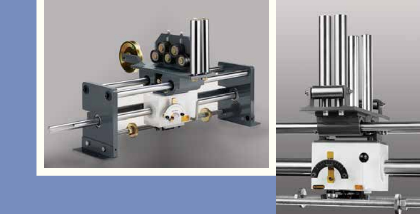
Traverse Assembly
Traverse assemblies are expertly tailored to meet the unique needs of our customers. We take into consideration several essential factors during customization
Maximum Traverse Stroke Length
Our versatile range includes shafts of varying lengths, extending up to 4000 mm, providing
you with options to suit your specific requirements.
Guide Assembly Requirement
We can incorporate suitable guide assemblies.
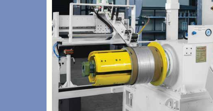
Load Carrier
Option to attach a load carrier equipped with linear bearings to the Rollring assembly, . This
feature effectively reduces the direct load imposed on the traverse unit, enabling it to handle
substantial loads with ease.
Our commitment to customization ensures that you get a traverse assembly perfectly tailored to your needs, whether you require extended stroke lengths, guide assemblies, or the ability to handle heavy loads."
A traverse assembly encompasses key components such as the Traverse unit, Shaft, Mounting brackets, Steady rail, Reversal end limits, and guide assemblies. When dealing with heavy loads, excessive winding tension, or guide overhang, it's advisable to incorporate a Load carrier with linear bearings supported on Guide shafts / Rail for improved performance.
Shaft Specifications: The shaft plays a vital role and should have specific attributes for
optimal performance:
Shaft Specifications: Material: C 45
- Shaft Straightness: Within 50µ per 300 mm
- Surface hardness around 58 to 60 Hrc
- Surface finish and straightness
- Tolerance on diameter: g6
- Heat treatment: High-frequency induction hardening
- Depth of effective hardness: 1 to 2.8 mm
- Corrosion protection: Hard chrome
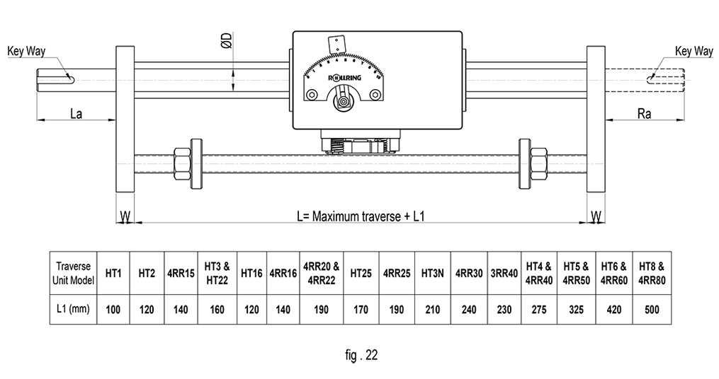
Shaft Length: Minimum length between support brackets = Maximum stroke length + L1 (L1 is related to the length of the traverse unit)
Refer fig 22 below
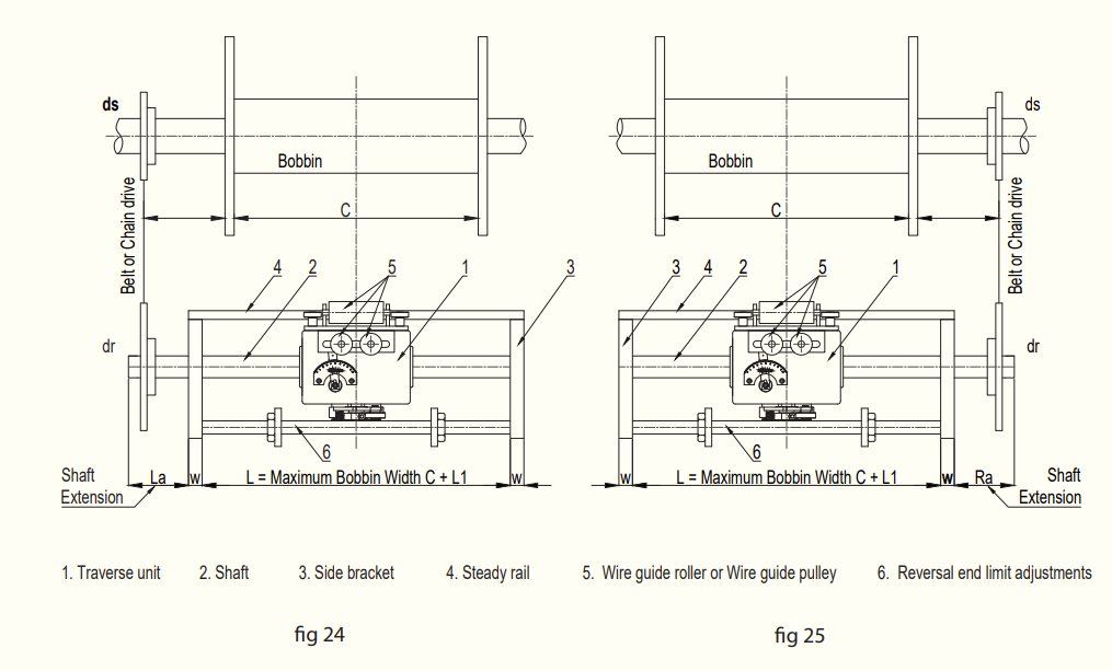
Components
- Guide Rail: Prevents traverse unit rotation on the shaft. Guide Bearing movement should be unhindered on the rail.
- Mounting Bracket: Supports the shaft on a bearing.
- Guide Assembly: Four tapped holes on the traverse unit's top side allow guide assembly mounting. Ensure bolt length adheres to specifications to prevent damage.
- Reversal End Limits: Threaded shaft with nut or plain shaft with adjustable stopper for altering stroke length.
- Load Carrier: Reduces load applied to the traverse unit, enabling traversing of heavy loads. Suitable for applications with heavy guide assemblies, high tension, twisting force, etc.
Bearing-Mounted Load Carrier: A plate with radial roller bearings, mounted on the traverse unit, supported by a rail. Suitable for normal applications
Load Carrier with Linear Bearing and Guide Shaft: Four linear bearings on a load carrier coupled to traverse unit. Guide assemblies are mounted on the load carrier. Ideal for heavy loads.
Load Carrier with LM Block and Rail: Four LM Blocks on two Rails mounted on a machined plate. Suitable for very heavy loads.
Bellows: Bellow type covers are provided on the shaft to prevent accumulation of dust and particles to prevent wear out of Rolling rings and shaft. Specifically for dusty environment
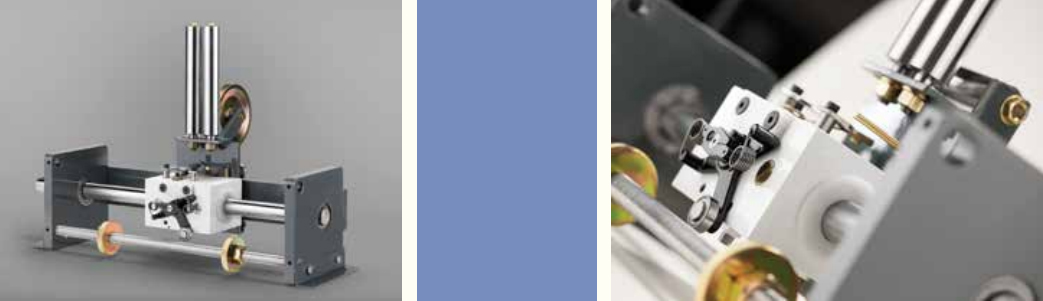
For vertical take-up or winding, traverse units can operate on vertically mounted shafts. Load carrier with linear bearings and guide shafts is recommended for mounting wire guide pulleys. A counterweight equivalent to the traverse unit's weight is suggested to reduce upward movement force.
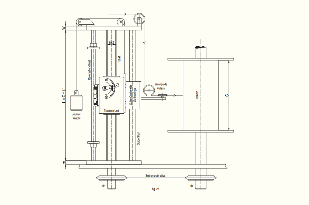
A small motor facilitates remote variation of traverse reversal end limit positions.
Bi conical bobbin winding: In the case of biconical bobbin winding, end limits shift as required during winding, sensing the number of bobbin rotations with PLC control. Stroke length increases as needed based on wire diameter and bobbin taper, controlled by a small PLC.
Note : Incorporating these components and considerations ensures the optimal performance and adaptability of traverse assemblies across a wide range of applications.
Download Catalogue