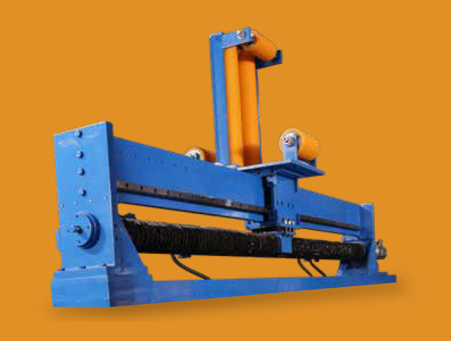
Traverse Assembly
Our traverse assemblies are meticulously designed to meet the specific needs of our customers.
Customization of Traverse Assemblies
Our traverse assemblies are expertly tailored to meet the unique needs of our customers, with several essential factors considered during customization :
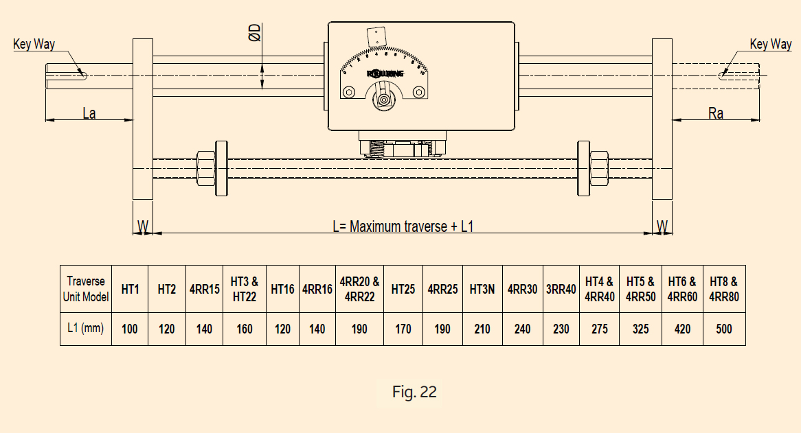
1. Maximum Traverse Stroke Length
Our traverse assemblies are expertly tailored to meet the unique needs of our customers, with several essential factors considered during customization:
2. Guide Assembly Requirements
We can incorporate appropriate guide assemblies to match your application.
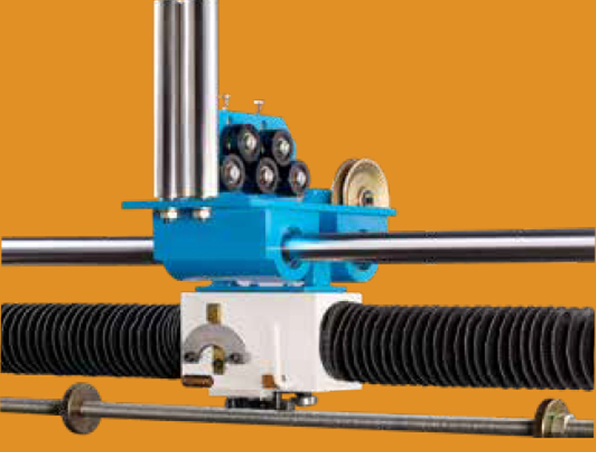
3. Load Carrier
We offer the option to attach a load carrier equipped with linear bearings to the Rollring assembly. This feature effectively reduces the direct load on the traverse unit, enabling it to handle substantial loads with ease.
Our commitment to customization ensures that you receive a traverse assembly perfectly tailored to your needs, whether you require extended stroke lengths, guide assemblies, or the ability to handle heavy loads.
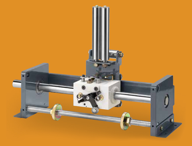
Traverse Assembly Components
A traverse assembly typically includes the following key components:
- 1. Traverse Unit
- 2. Shaft
- 3. Mounting Brackets
- 4. Steady Rail
- 5. Guide Assemblies
- 6. Reversal End Limits
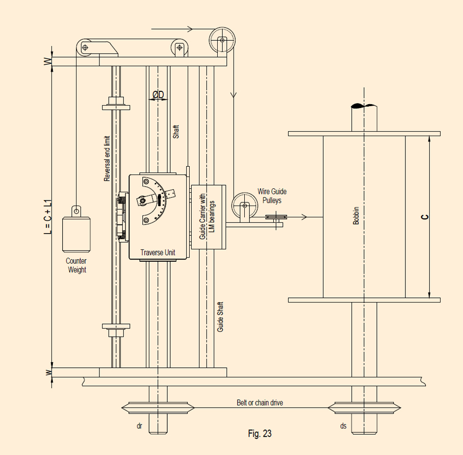
refer figure 16/17
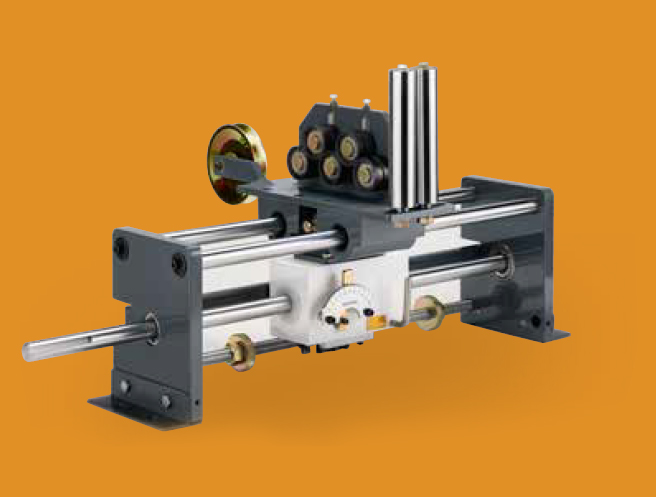
When dealing with heavy loads, excessive winding tension, or guide overhang, it's advisable to incorporate a load carrier with linear bearings supported on guide shafts/rails for enhanced performance.
Shaft Specifications
The shaft is critical for optimal performance and should possess the following attributes:
- Material: C45
- Shaft Straightness: Within 50μ per 300 mm
- Surface Hardness: 58 to 60 HRC
- Surface Finish and Straightness
- Tolerance on Diameter: g6
- Heat Treatment: High-frequency induction hardening
- Depth of Effective Hardness: 1 to 2.8 mm
- Corrosion Protection: Hard chrome plating
Shaft Length:
The minimum length between support brackets should equal the maximum stroke length plus L1 (where L1 relates to the length of the traverse unit).
(Refer to Figure 23)
Key Components
1. Guide Rail
Prevents the traverse unit from rotating on the shaft. Ensure that the guide bearing moves
unhindered along the rail.
2. Mounting Bracket
Supports the shaft on a bearing.
3. Guide Assembly
The traverse unit's top side features four tapped holes for guide assembly mounting. Ensure the bolt
length adheres to specifications to prevent damage.
4. Reversal End Limits
Use a threaded shaft with a nut or a plain shaft with an adjustable stopper to alter the stroke length.
Load Carrier
Reduces the load applied to the traverse unit, enabling it to handle heavy loads. This is particularly useful for applications with heavy guide assemblies, high tension, or twisting forces.